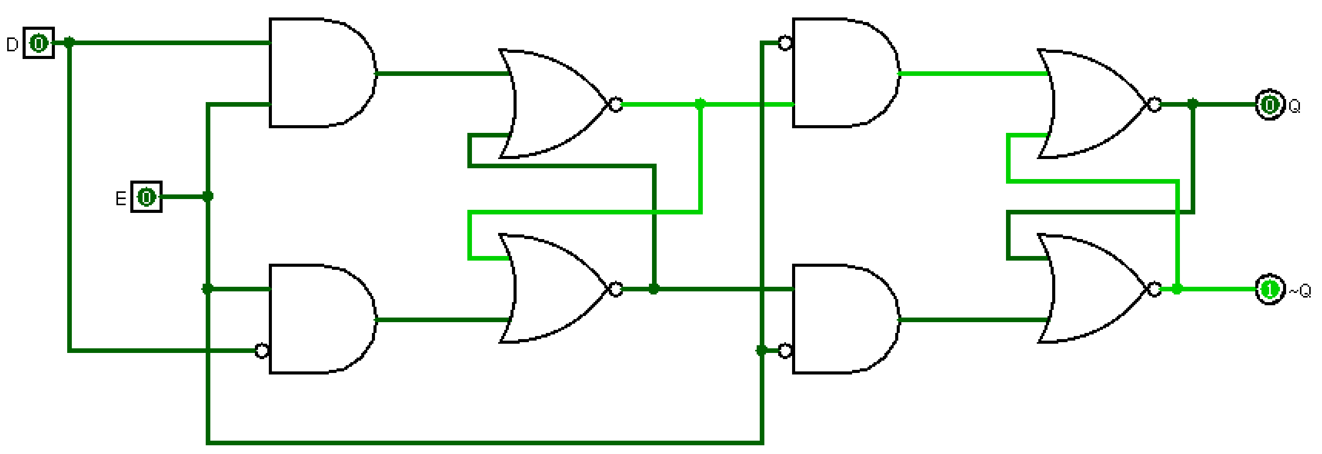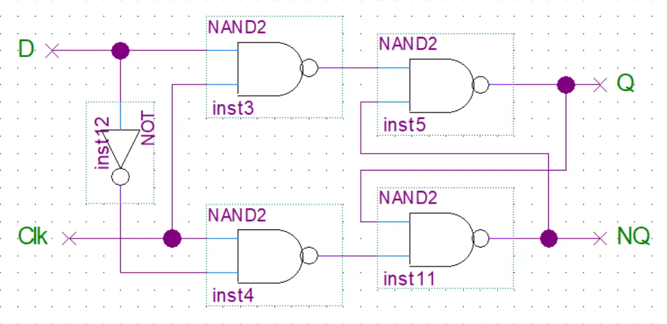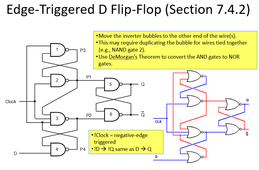


Such data storage can be used for storage of state, and such a circuit is described as sequential logic in electronics. A flip-flop is a device which stores a single bit (binary digit) of data one of its two states represents a "one" and the other represents a "zero". Flip-flops and latches are fundamental building blocks of digital electronics systems used in computers, communications, and many other types of systems.įlip-flops and latches are used as data storage elements. It is the basic storage element in sequential logic. The circuit can be made to change state by signals applied to one or more control inputs and will have one or two outputs. In electronics, a flip-flop or latch is a circuit that has two stable states and can be used to store state information – a bistable multivibrator. An animated interactive SR latch ( R1, R2 = 1 kΩ R3, R4 = 10 kΩ). Problem, the output of circuit can ’ t beĬounter. If a circuit suffers “Clock Skew “ problem, the output of circuit can ’ t be guarantied. The terminal count of a 4-bit binary counter in the UP mode is _ The terminal count of a 4-bit binary counter in the DOWN mode is _ _is oneof the examples of asynchronous inputs. Master- Slave flip- flop does notoperate on pulses, rather it isedge triggered.Ī negative edge-triggered flip-flop changes its state when_ InMaster-Slave flip-flop setup, the master flip flop operates at _ _is said to occur when multiple internal variables change due to change in oneinput variable on the next clockpulse, to what state does the counter go ? It does notshow transition on change in pulseĭivide- by-32 counter can be acheived by usingĪ 4- bit UP/DOWN counter isin DOWN mode and in the 1010 state. The operation of J-K flip-flop issimilar to that of the SR flip-flop except that the J- K flip-flop _ The glitches due to "Race Condition" canbe avoided by using a _ In a 4-bit binary counter, the next state after the terminal count in the DOWN mode is _Īn Astable multivibrator is known as a (n) _Ī synchronous decade counter will have _flip-flops The minimum time required for the input logic levels to remain stable before the clock transition occurs is known as the _ Different parts of circuit operate at different clock frequencies (4 MHZ, 2 MHZ and 1 MHZ), but we have a single clock source having a fix clock frequency (4MHZ), to supply the required frequency to each part of circuit, we can get help by using _Įach stage of Master-slaveflip- flop works at _ of the clocksignalĪ modulus-14 counter has fourteen states requiring_

If a circuit suffers “Clock Skew “ problem, the output of circuit can’t be guarantied.Ī positive edge-triggered flip-flop changes its state when _ (“n” represents the total number of flip-flops) The counter states or the range of numbers of a counter is determined by the formula. The Synchronous counters are also known as Ripple Counters: Three cascaded modulus-10 counters have an overall modulus of The _ input overrides the _ inputĭivide-by-160 counter is acheived by usingĪn Astable multivibrator is known as a(n) _ Input Hold time is zero (no need to maintain input after clock transition) Propagation Delay is zero (Output is immediately changed when clock signal is applied) The changes in the data at the inputs of the latch are not seen at the output

The changes in the data at the inputs of the latch are seen at the output The output of flip-flop remains unchanged When the both inputs of edge-triggered J-K flop-flop are set to logic zero _ A counter is implemented using three (3) flip-flops, possibly it will have _ maximum output status.Ī mono -stable device only has a single stable state


 0 kommentar(er)
